SD/MMC mod
From DD-WRT Wiki
| Revision as of 09:17, 8 July 2007 (edit) Iron (Talk | contribs) ← Previous diff |
Revision as of 09:43, 8 July 2007 (edit) (undo) Iron (Talk | contribs) Next diff → |
||
| Line 5: | Line 5: | ||
| '''1. Introduction''' | '''1. Introduction''' | ||
| - | This tutorial guides you through adding a SD/MMC interface to the Buffalo WHR-G54S router and gives some general information and tips that help you to do the same with other routers. Applying this modification to the Buffalo WHR-HP-G54S will be almost identical | + | This tutorial guides you through adding a SD/MMC interface to the Buffalo WHR-G54S router and gives some general information and tips that help you to do the same with other routers. Applying this modification to the Buffalo WHR-HP-G54S will be almost identical to what is described here. |
| Line 15: | Line 15: | ||
| '''3. Finding suitable IO points''' | '''3. Finding suitable IO points''' | ||
| - | + | Once you have opened the router you will have access to the printed circuit board(PCB). | |
| - | + | On this board we need to find several points that we are going to use to build our SD/MMC interface. | |
| + | 1) A ground access point | ||
| + | 2) A power supply of 3.3 volt | ||
| + | 3) Three general IO output points | ||
| + | 4) One general IO input point | ||
| + | |||
| + | To find these points we will need our general purpose friend, the multi-meter. | ||
| + | |||
| + | 3.1 Ground access point | ||
| + | |||
| + | It is usually very easy to find a grounded point, because ground is present all over the PCB. Usually the input power ground will also be the ground level for the whole PCB. So start looking at the input power socket. This socket usually has quite big soldering points which makes it easy to add an extra wire. Once this point is found verify it by checking big metal object on the PCB. Usually the metal housing around the tuner (see pictures below) will be grounded too. To verify that the points are connected use the conductivity check of the multi-meter. Make sure the router is powered down. The connection between the points should give you a very low number, about the same number you would get when just shorting your multi-meter probes. | ||
| + | With the Buffalo WHR-G54S I found that the metal mounting pins for a switch were also grounded. This gives me an easy access point, and is also a nice point for the routing of the wires. I don't like to access different point all over the PCB. | ||
| + | |||
| + | 2) A power supply of 3.3 volt | ||
| + | |||
| + | One a grounded point is found we can start looking for the 3.3 volt power supply that we need. Check your power supply specification. Check if it provides AC or DC at the output. AC is indicated with a waived line (~), while DC is indicated with 2 straight lines. One of the lines is interrupted. If the output indicates that the power supply is 3.3 volt already, then check the power socket at the PCB for 3.3 volt. To verify this you need to power up the router. Be very careful with this, as it is very easy to short circuit the board with some parts lying around. Switch the multi-meter to DC volt measurement, 0-20 volt. The actual value that you find might be slightly higher or lower (3.1-3.5 volt). If you power supply is higher than 3.3 volt than the PCB will usually contain a power regulator to lower the input voltage to 3.3 volt. You will need to find this power converter, and it's output. The power converter is usually a big component, close to the input power socket. Power up the router and carefully probe the big pads of the big components close to the power socket. | ||
| while true; do gpio disable 2; sleep 1; gpio enable 2; sleep 1; done | while true; do gpio disable 2; sleep 1; gpio enable 2; sleep 1; done | ||
| Use negative side of LED (+ side is marked). | Use negative side of LED (+ side is marked). | ||
| - | |||
| [[Image:WHR_G54S_SD_MOD-Telnet_DOS_BOX.png]] | [[Image:WHR_G54S_SD_MOD-Telnet_DOS_BOX.png]] | ||
Revision as of 09:43, 8 July 2007
SD/MMC Mod for the Buffalo WHR-G54S
This is a work in progress...
1. Introduction
This tutorial guides you through adding a SD/MMC interface to the Buffalo WHR-G54S router and gives some general information and tips that help you to do the same with other routers. Applying this modification to the Buffalo WHR-HP-G54S will be almost identical to what is described here.
2. How to open your router
Check this Wiki How to open the Buffalo WHR-HP-G54 to see how to open your router without breaking it.
3. Finding suitable IO points
Once you have opened the router you will have access to the printed circuit board(PCB). On this board we need to find several points that we are going to use to build our SD/MMC interface. 1) A ground access point 2) A power supply of 3.3 volt 3) Three general IO output points 4) One general IO input point
To find these points we will need our general purpose friend, the multi-meter.
3.1 Ground access point
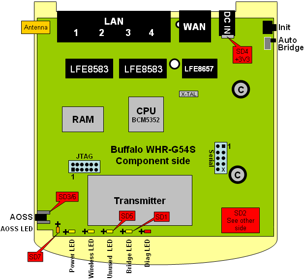
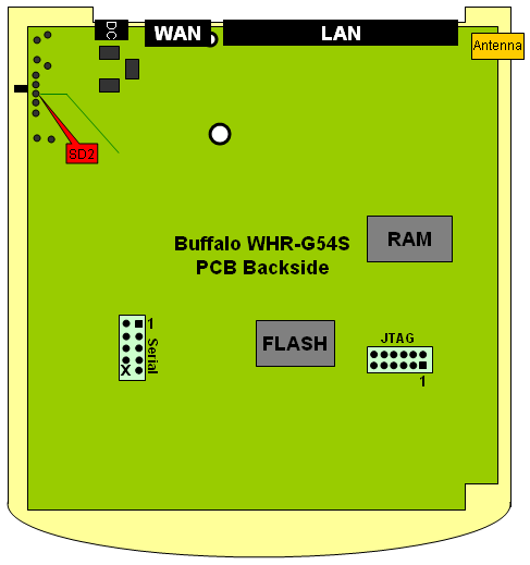
It is usually very easy to find a grounded point, because ground is present all over the PCB. Usually the input power ground will also be the ground level for the whole PCB. So start looking at the input power socket. This socket usually has quite big soldering points which makes it easy to add an extra wire. Once this point is found verify it by checking big metal object on the PCB. Usually the metal housing around the tuner (see pictures below) will be grounded too. To verify that the points are connected use the conductivity check of the multi-meter. Make sure the router is powered down. The connection between the points should give you a very low number, about the same number you would get when just shorting your multi-meter probes. With the Buffalo WHR-G54S I found that the metal mounting pins for a switch were also grounded. This gives me an easy access point, and is also a nice point for the routing of the wires. I don't like to access different point all over the PCB.
2) A power supply of 3.3 volt
One a grounded point is found we can start looking for the 3.3 volt power supply that we need. Check your power supply specification. Check if it provides AC or DC at the output. AC is indicated with a waived line (~), while DC is indicated with 2 straight lines. One of the lines is interrupted. If the output indicates that the power supply is 3.3 volt already, then check the power socket at the PCB for 3.3 volt. To verify this you need to power up the router. Be very careful with this, as it is very easy to short circuit the board with some parts lying around. Switch the multi-meter to DC volt measurement, 0-20 volt. The actual value that you find might be slightly higher or lower (3.1-3.5 volt). If you power supply is higher than 3.3 volt than the PCB will usually contain a power regulator to lower the input voltage to 3.3 volt. You will need to find this power converter, and it's output. The power converter is usually a big component, close to the input power socket. Power up the router and carefully probe the big pads of the big components close to the power socket.
while true; do gpio disable 2; sleep 1; gpio enable 2; sleep 1; done
Use negative side of LED (+ side is marked).
Required tools: Soldering iron with a very fine tip. Some pieces of thin wire (diameters approx. 0.25 mm) A SD card adapter. A SD or MMC card.
Image:WHR G54S SD MOD-Management Screen.png


