LaFonera Hardware Cooling-System
From DD-WRT Wiki
| Revision as of 06:08, 20 March 2007 (edit) Wildblue (Talk | contribs) m ← Previous diff |
Revision as of 06:11, 20 March 2007 (edit) (undo) Wildblue (Talk | contribs) Next diff → |
||
| Line 88: | Line 88: | ||
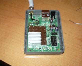
| Notes: The switch mod is really straight forward and should require little to no imagination. Just do it. | Notes: The switch mod is really straight forward and should require little to no imagination. Just do it. | ||
| + | |||
| + | == extending this mod == | ||
| + | # Maybe we should add a GPIO Connector to control the cooling fan. | ||
| + | # Also we could add a temprerature control. | ||
Revision as of 06:11, 20 March 2007
Cooling System MOD - Hemi with optional NOS Button .... oh Yeah....
So these things run pretty hot...
And if any of the pictures I've seen are true I'm not looking forward to my case melting and destroying itself.
Also not a big fan of capacitors that will only last 382 days at standard heat rating of this unit.
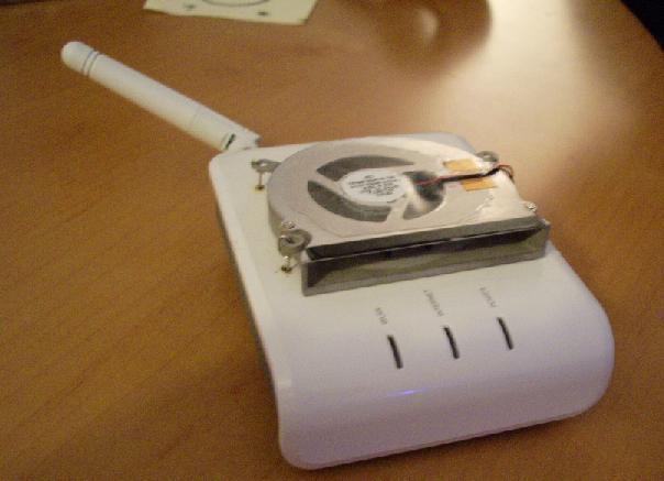
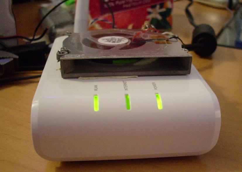
So to extend the life of this nifty little unit we shall simply add a clutch looking fan to the top. (how the fan looks is not really significant to its operation)
What we need
- Fonera
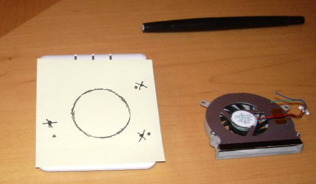
- Small Laptop Fan
- Switch(optional)
- Screw Driver
- Soldering Iron
- Solder
- Really Small Wire
- Resistors (optional,size depends on fan needs)
- Pliers
- Blow Torch
- Razor Blade
- Permanent Marker
- Post-it Notes
- Hot Glue
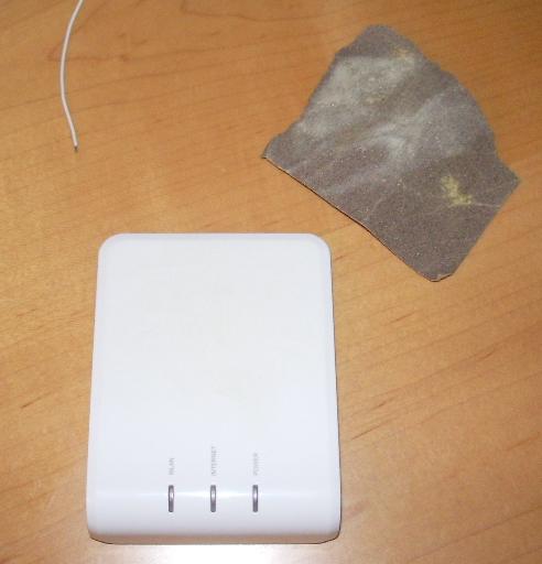
- Sand Paper
This is how we do...
1. First remove the top cover by taking out the screws hidden under the two front rubber feet.
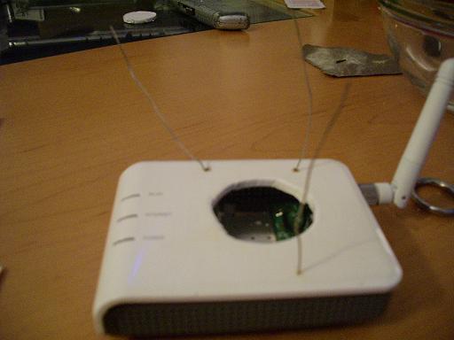
2. Stick the Post-it on the cover and then draw on the Post-it the size of the hole you want and where the anchor points will be.
2a. Now is about when you should remove the "Fon" logo with sand paper.
3. After making sure you have the right placement on the cover. Transfer the marked hole and points through the paper by holding the marker down a bit.
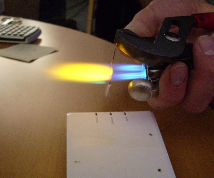
4. Melt the anchor holes with pliers and hot wire. Then cut the vent hole with heated razor blade.
5. Place blobs of solder at one end of the anchor wire. Once cool, insert the other end through the underside of the cover.
Right about now, the Author recommends, you should replenish the calcium, glucose, and vitamin C your brain has used up during this mod.
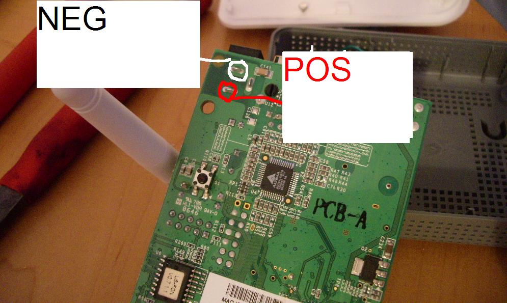
6. Stick the fan leads through the tiny vent holes on the side. Solder the leads to the positive and negative pins on board.
7. Replace the cover. Anchor the fan down by bending the leads. Replace the screws.
8. Use the glue gun to secure around the fan so it doesn't rattle too much. (Use it for the optional switch as well.)
Plug in and watch it spin!
Notes: The switch mod is really straight forward and should require little to no imagination. Just do it.
extending this mod
- Maybe we should add a GPIO Connector to control the cooling fan.
- Also we could add a temprerature control.

