Upgrading WL-500g Premium WL-500W and WL-700gE RAM to 128MB
From DD-WRT Wiki
Contents |
[edit] Introduction
The goal of this mod is to increase built in memory up to 128MB to be able run more services on the router without the expense of accessing slow swap, etc. Beware, that this mod requires very strong soldering skills! And usual disclaimer: do it on your own risk to brick the router completely.
[edit] What do you need to perform a mod?
- Good soldering skills at first (the board is Pb Free!) and equipment
- One 22Ohm (33 Ohm is also ok) resistor to enable A12 address line (not needed for WL-700gE, as it has it already)
- Two TSOP packaged DDR333 or DDR400 SDRAM chips organized as 32Mx16
The easiest way to get chips (and perhaps cheap) is to remove them from the PC2700/PC3200 DIMM or SO-DIMM: at the moment we've checked the following parts:
- Hynix HYMD532646CP6J-D43 PC3200 DIMM: it has Hynix HY5DU121622CTP-D43 chips
- Samsung M470L6524BT0-CB3 PC2700 SO-DIMM: it has Samsung K4H511638B-TCB3 chips
- Samsung M470L6524DU0-CB3 PC2700 SO-DIMM: it has Samsung K4H511638D-UCB3 chips
- Transcend TS32MSD64V3M PC2700 SO-DIMM: it has Elpida D5116AFTA-5B-E chips
Please note, that Hynix is least preferred. Also, avoid using Infineon chips. The problem is that PCB is not ideally traced and has some noise UDQS line coming to U4, resulting in memory errors (see below).
[edit] Doing It
- Note this may require a special firmware build.
- Telnet/ssh to your router and type
nvram set sdram_init=0x000b
nvram set sdram_config=0x0032
nvram commit
halt
This would turn U4 chip off and prevent my firmware from auto enabling it. The router would be halted too, so you could safely remove power from it.
- Disassemble your router now
- Remove shieldings from the back of PCB (it's self-adhesive) and from the top
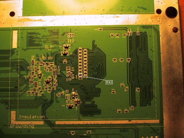
- Solder 22 Ohm resistor on the free pads labeled R43. Skip this step if you have WL-700gE. Check image below:
- Replace original U3 chip with your new memory chip. Be sure to remove PB free solder completely from the PCB pads before soldering your new chip!
- Power your device on. It should now start normally and report 32MB of RAM (use free to check this). If it does not check, then your soldering work again. Don't even think of pin-9 trick or whatever! FYI: all routers starts after replacing U3 chip.
- Test RAM using memtest (see below). If it fails, then double check your soldering and try again.
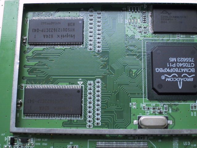
- Given, that your router works with U3 replaced continue with replacing U4, now it should look like this:
- Replaced? Ok, turn it once again and check, that it still work. If it does not check U4 soldering - perhaps you've shortcircuited something... Now type the following in the telnet/ssh to enable U4 and 128MB of RAM:
nvram set sdram_init=0x0011
nvram set sdram_config=0x0062
nvram commit
reboot
- It should now reboot. If it does, than you're lucky man (Elpida and Samsung chips are reported to be lucky) if it does not (Hynix never boots this way) then proceed this way: check your U4 soldering work once again. Try to power on your device. If everything looks good then you can to try adding 3-7 pF capacitor between U4 pin 51 (UDQS) and ground:
- If it does not boot - check your soldering work once again. If it still does not work - I've no idea then. Don't blame me, this is ASUS PCB fault.
- Test RAM using memtest (see below). Leave it running for a long time to be absolutely sure it works fine. If it does not, then perhaps you should solder a capacitor as described above. Once it's error free, you could tell memory controller to re-tune some internal timings:
nvram set sdram_ncdl=0
nvram commit
reboot
[edit] Activating 128MB with known good memory
You need this everytime you perform a reset to defaults... add it as a script, see Index:Scripting, save it as command, so you can run it when you want to, right from the web GUI.
nvram set sdram_init=0x0011
nvram set sdram_ncdl=0
nvram commit
reboot
[edit] Testing device memory
Type these lines to start testing:
cd /tmp
wget http://oleg.wl500g.info/bin/memtest
chmod +x memtest
./memtest 16m
- Note, that memtest at most could only pin half of device memory at a time. Replace 16m with 64m for 128MB of RAM.
[edit] Pictures
[edit] WL-700gE with Samsung chips and 8MB flash
[edit] WL-500gP with Samsung and Hynix chips at the same time
Samsung chip does not need caps on this PCB...

[edit] Links
This "how to" is nearly a direct copy from: Upgrading WL-500g Premium, WL-500W and WL-700gE RAM to 128 MB All credit to the original author.


